Retro Joystick Control
Suppose you have an old joystick that you want to use to control your latest micro-controller project. These joysticks use a DB-15 connector with a readily available pinout. A Game Port style joystick consists of digital buttons, and analog axes. In this post, I will go over how to optimally interface the axes of these types of joysticks with your microcontroller.
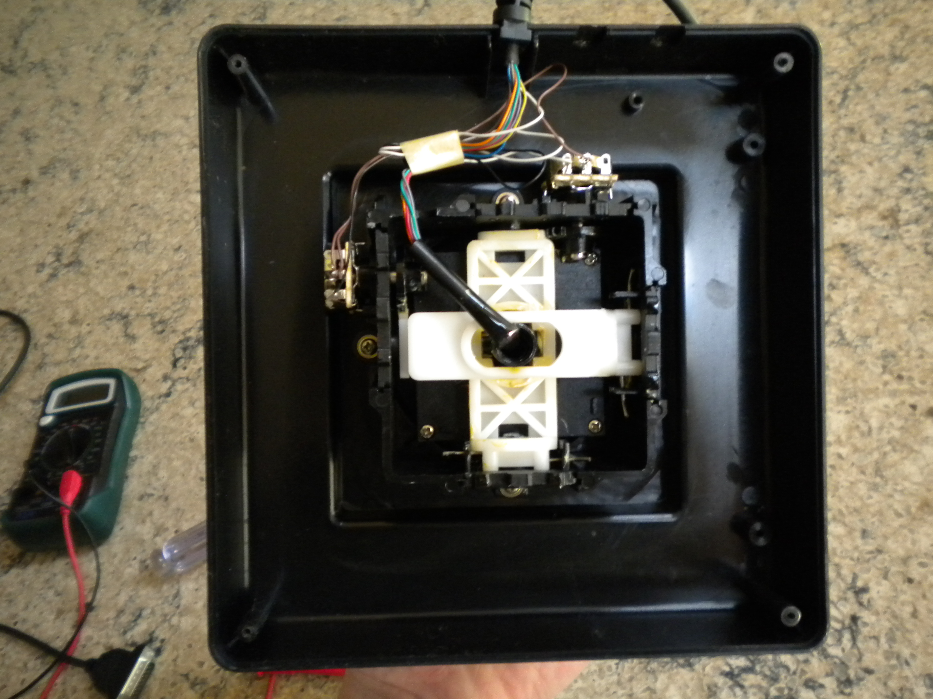
Inside of the joystick, mounted at right angles are potentiometers, one for each axis:
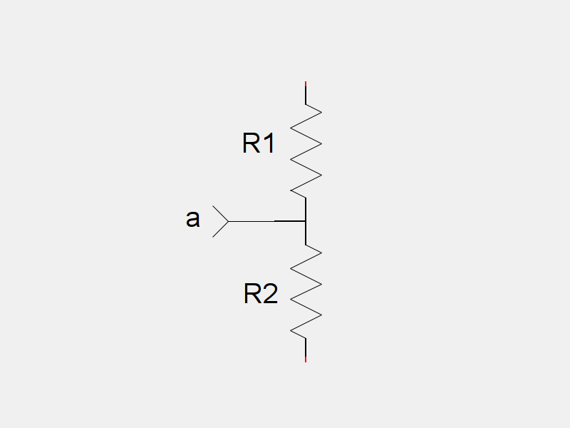
A potentiometer is a very basic electrical sensor. The voltage output of an angular potentiometer is directly proportional to the angle of its shaft relative to its case. The symbol for a potentiometer looks like this:

A potentiometer functions like two resistor connected in series (back to back).
As the angle of the potentiometer changes relative to its case, the resistance of the two resistors changes according to the following function:
$$ \begin{align} R_1 =R_{max}-k\theta \quad & \quad R_2 = k\theta \end{align} $$
Where $R_1$ and $R_2$ correspond to the resistors in the above equivalent circuit, $R_{max}$ is the maximum resistance of the potentiometer, $\theta$ is the current angle of the potentiometer, and k is a constant corresponding to:
$$ k=\frac{R_{max}}{\theta{}_{max}} $$
Where $R_{max}$ is the aforementioned maximum resistance and, $\theta_{max}$ is the maximum angle of the potentiometer. Using this equation, you can determine the $k$ value for this potentiometer.
According to Digikey, this potentiometer has a rotation radius $\theta_{max}$ of 270 degrees. It also has a resistance $R_{max}$ of 100,000 ohms. This means it has a $k$ value of:
$$ k = \frac{R_{max}}{\theta_{max}} = \frac{100000}{270^\circ} \approx 370.4 $$ Since the values of these resistors change depending on the current angle of the potentiometer, it would make sense to rewrite them as functions:
$$ \begin{align} r_1(\theta) =R_{max}-k\theta \quad & \quad r_2(\theta) = k\theta \end{align} $$
Ohm’s Law says that voltage is equal to current times resistance. If you were to connect a constant voltage source across the outside terminals of our potentiometer:
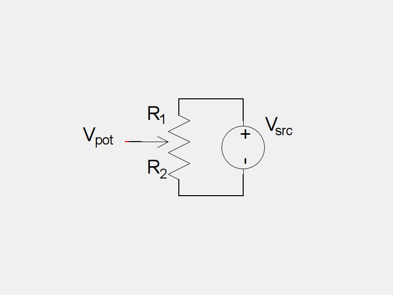
The current, $I_{pot}$ through $R_1$ and $R_2$ can be found:
$$ \begin{align} V & = IR \ I & = \frac{V}{R} \ I_{pot} & = \frac{V_{src}}{R_{pot}} \end{align} $$
Since the two resistor halves of the potentiometer are in series, their resistance adds:
$$ R_{pot} = r_1(\theta)+r_2(\theta) $$
This gives us
$$ I_{pot} = \frac{V_{src}}{r_1(\theta)+r_2(\theta)} $$
If you were to insert a miniature current sensor right into the middle of the potentiometer, this is the current that it would measure. Unfortunately, in the real world, miniature current sensors are hard to come by. We would like some way determine the angle of the potentiometer using the voltage at its middle point.
If we say that the negative terminal of the voltage source has a voltage of zero volts, then the voltage at the middle of the potentiometer is equal to the voltage across $R_2$:
$$ V_{pot} = V_2 $$
How do we find the voltage across $V_2$? We use Ohm’s Law again:
$$ \begin{align} V & = IR \ V_2 & = I_{pot} \cdot R_2 \ V_2 & = \frac{V_{src}}{r_1(\theta)+r_2(\theta)} \cdot r_2(\theta) \ V_2 & = V_{src} \cdot \frac{k\theta}{R_{max}-k\theta + k\theta} \ V_2 & = V_{src} \cdot k \cdot \frac{\theta}{R_{max}} \ V_2 & = V_{src} \cdot \frac{R_{max}}{\theta_{max}} \cdot \frac{\theta}{R_{max}} \ V_2 & = V_{src} \cdot \frac{\theta}{\theta_{max}} \ V_{pot} & = V_{src} \cdot \frac{\theta}{\theta_{max}} \end{align} $$
In other words, the voltage outputted by the potentiometer is directly proportional to the angle of the potentiometer. This is useful. It means that if you can measure the voltage of a potentiometer, you can easily determine its angle, given its maximum rotation.
For example, suppose that the $270^\circ$ potentiometer from before is connected to your microcontroller. Assume the source voltage for the potentiometer is 5 volts. If you read 3.7 volts on the potentiometer, you can easily calculate its angle:
$$ \begin{align} V_{pot} & = V_{src} \cdot \frac{\theta}{\theta_{max}} \ \theta & = \frac{V_{pot}}{V_{src}} \cdot \theta_{max} \ \theta & = \frac{3.7}{5} \cdot 270^\circ \ \theta & = 199.8^\circ \end{align} $$
The potentiometer must be at an angle of approximately 200 degrees.
It makes sense that joysticks would use potentiometers to determine its position. However, the potentiometers are not hooked up in the standard way:
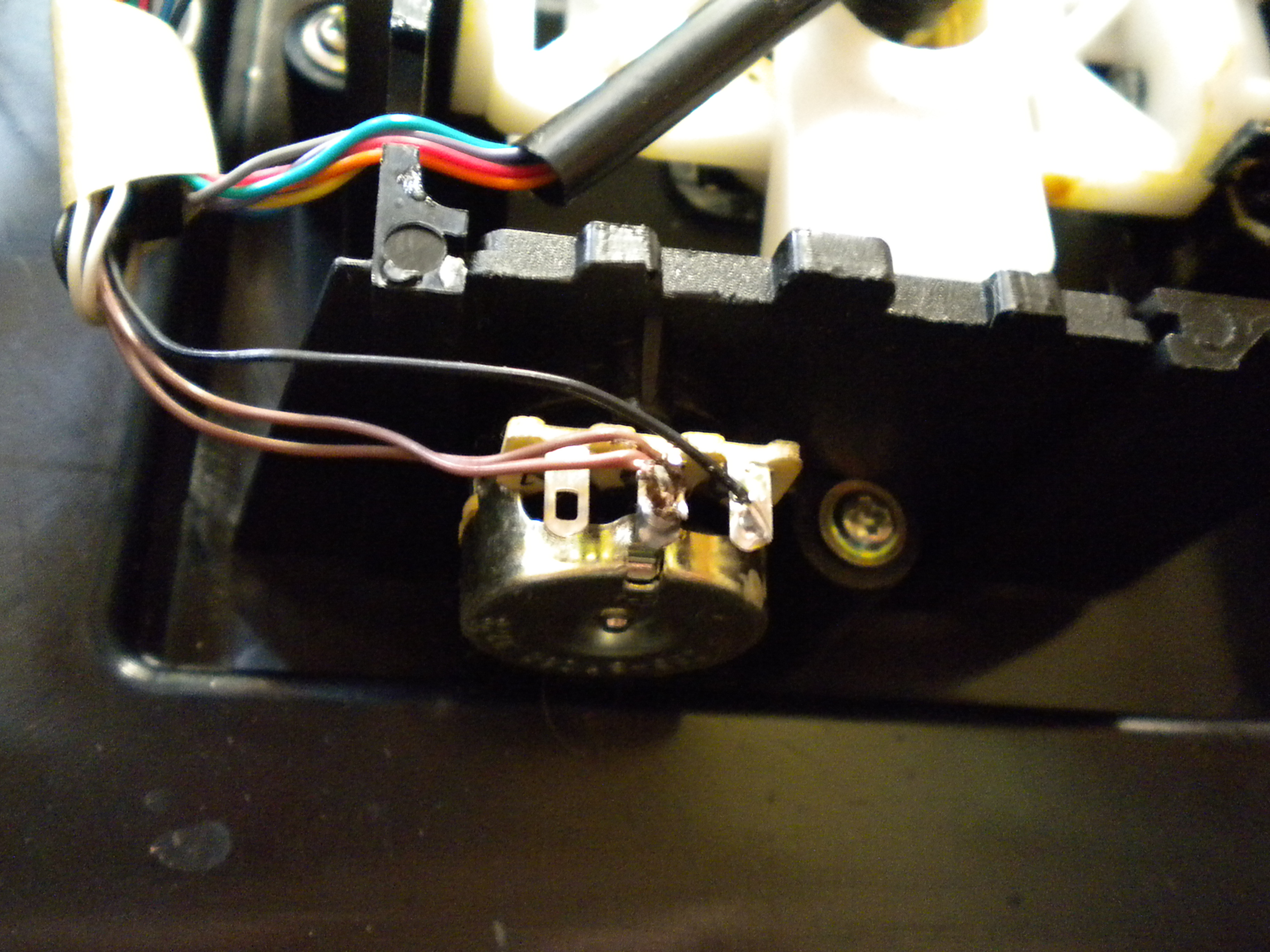
In the above picture, you will notice that only two of the terminals of the potentiometer are hooked up. In this arrangement, the potentiometer is functioning as a variable resistor: Its resistance is directly proportional to the angle of the shaft. The circuit for these potentiometers looks like this:
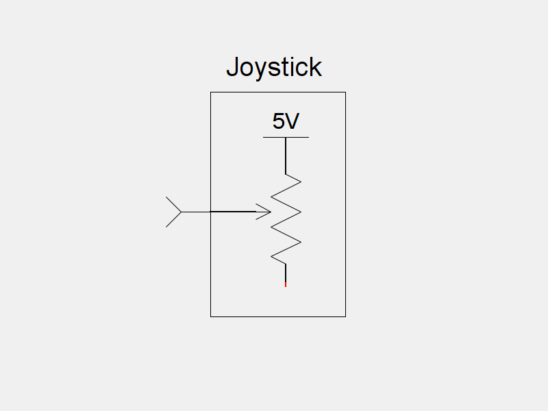
You can see that the bottom terminal of the potentiometer (the little red bit) is not connected to anything. There is a historical reason for this. When IBM first developed the Game Port for the original IBM-PC, they wanted to use cheaper timing based solutions to measure the deflection of the joystick axes. The time it took for a timer to trigger would be proportional to the resistance of the potentiometer, which would in turn be proportional to the angle of the potentiometer. Nowadays, microcontrollers have built in analog-to-digital converters, obviating the need for any kind of timer. Unfortunately for us, the decades old Game Port design won’t work directly with a modern microcontroller: It outputs a variable resistance, and we want a variable voltage.
There are two solutions to this problem, with different trade offs for each.
The easiest solution is to connect a resistor to the joystick connector for this axis:
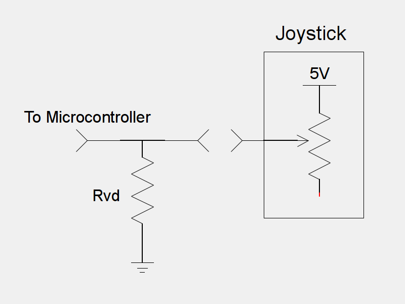
This circuit looks a lot like the circuit we had for the basic potentiometer, exception that the resistance of the $R_2$ is constant. To find the voltage that would be seen by a microcontroller, we again need to calculate the current through the joystick resistor, and the other resistor:
$$ \begin{align} V & = IR \ I & = \frac{V}{R} \ I_{pot} & = \frac{5}{R_{pot} + R_{vd}} \end{align} $$
Once we have an equation for $I_{pot}$, we can easily find an equation for $V_\mu$:
$$ \begin{align} V & = IR \ V_\mu & = I{pot} \cdot R_{vd} \ V_\mu & = \frac{5 R_{vd}}{R_{pot}+R_{vd}} \end{align} $$
Assuming that the range of the potentiometer is from 0 ohms to 100 ohms, we can see that this function is not linear. As the resistance of the potentiometer changes, the voltage that the microcontroller sees also changes, but they are not related linearly. Also, the voltage depends on the value of $R_{vd}$ chosen. Listed below are graphs of the microcontroller’s voltage for several different values of $R_{vd}$:

Assume that when the joystick has a resistance of 50k ohms when it is at rest in the middle. It makes sense, then, that when it is fully extended in one direction, its resistance would be 100k ohms, and when fully extended in the other direction, its resistance would be 0 ohms. You can see by looking at this graph that for some values of $R_{vd}$, the range of the output voltage $V_\mu$ is nowhere near the total range from 0 volts to 5 volts. Also, you can see that the range of $V_\mu$ for values less than 50k ohms is much larger than the range for values greater than 50k ohms. Practically, this means that when we deflect the joystick in one direction, we will get a larger change in voltage that if we moved it in the other direction. This is obviously less than ideal. However, this design does have some pros. We do not need to modify the joystick to implement this circuit, which means that we can still use this joystick with a computer.
Another way to solve this problem, is to modify the joystick, so that the potentiometers are hooked up in the standard way:
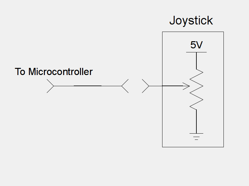
We have already seen that in this configuration, the voltage read by the microcontroller is directly proportional to the angle of the potentiometer. The downside to this method is that it requires modifying the joystick. Once this modification is made, you can’t plug the joystick into a computer anymore. However, the values read out of the joystick are much more accurate.
There are two different ways to attach a Game Port style joystick to a microcontroller. They both have their advantages, and their drawbacks. The external resistor solution requires a software algorithm to normalize the output of the potentiometer, while the potentiometer fix requires modifying the joystick’s hardware. The solution you choose is up to you.